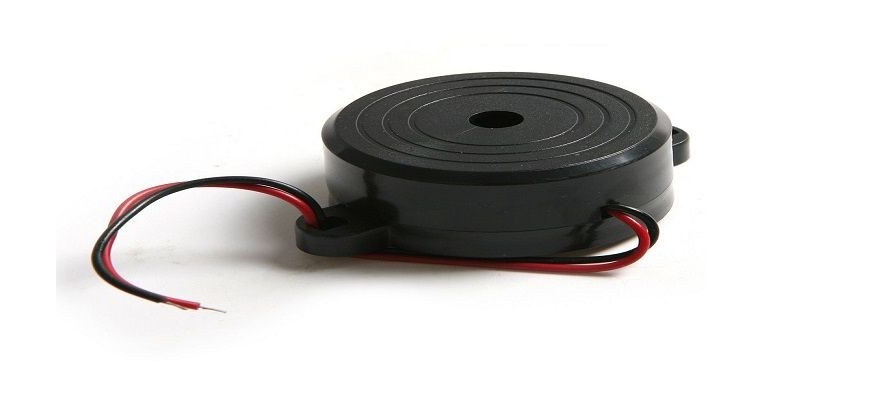
Buzzers are used as audio indication devices. These devices could be electro-mechanical or mechanical. Its usage comprises alarm notification and timers.
Electro-Mechanical Buzzers
Initial buzzer devices were based on the electro-mechanical procedure. These procedures are similar to that of a metal gong or electric bell.
Most of the time, its units were fixed to a ceiling or a wall and used as a sounding device.
Mechanical Buzzers
An example of a mechanical buzzer is Joy buzzer. The major characteristic of mechanical buzzers is the usage of drivers. A good example is a doorbell.
Proper usage of Buzzers
Despite being small, a buzzer is extremely efficient when dealing with quality sound features in a given system.
Buzzers can be customized for multiple purposes.
Buzzer Application
- Every Buzzer contains an alarming circuit used for notification purposes.
- As a result of the buzzers’ notification ability, buzzers can play a major role in communication.
- Buzzers can be used as machine equipment
- The portability of buzzers is also an added advantage.
A working rule of Buzzer Circuit
Magnetic buzzers are steered by a coil of wire which produces a magnetic field. Magnetic buzzers are quite different from the piezo buzzer.
As opposed to magnetic buzzers, piezo buzzers are made as capacitors while magnetic buzzers are designed with coils and resistors.
Basic description of SMD buzzer 5v
SMD active Buzzer 5v is a merged system of electronic transducers. It is created for DC power supply usage. More often than not, Smd buzzers are used in computers, printing devices, and electronic play tools.
SMD active buzzer 5v contains quality power which can be connected to a continuous sound.
Distinctive characteristics of SMD buzzer 5v
- Stagnant on-board buzzer
- On-board 8550 triode steer
- Possibility of being controlled by a single-chip microcontroller
- 5v working voltage power
- Cabinet size: 22(mm) x12 (mm)
Configuration code
- Ground
- Input
- VCC
Testing Procedure
Below is the testing procedure for SMD buzzer 5v
- Attach a micro-controller to the computer
- Attach the VCC pin to the module
- Attach the GND of the module to the GND pin of your Arduino
- Input the pin of the module
- Lastly, Click on the Upload button
Test running available results
The output button is used for turning the buzzer off and on. With the availability of necessary materials, the 5v Smd buzzer setup would take only a few minutes.
SMD active buzzer 5v specification
| No | Item | Unit | Specification | Condition |
| 1 | Fluctuation Frequency | KHz | 2.7+ 0.3 | |
| 2 | System Voltage | VDC | 4˜7 | |
| 3 | Rated Voltage | VDC | 5 | |
| 4 | Current Consumption | MA | MAX. 30 | At Estimated Volts supply |
| 5 | Sound Level | DB | MIN. 80 | At, 10cm, at Estimated volts supply |
| 6 | Mood Nature | Individual | ||
| 7 | Regulating Temperature | C | -20 ˜ + 70 | |
| 8 | Holding Temperature | C | -30 ˜ +85 | |
| 9 | Dimension | Mm | 9.6x 9.6x H5.0 | Vision diagram |
| 10 | Strength (MAX) | Gram | 1.5 | |
| 11 | Sheltering Equipment | PPS (Raven) | ||
| 12 | Heading Buckle | Plated Brass (Au) | Vision diagram | |
| 13 | Background Safety Requirement | RoHS |
Principle gauge conditions
Temperature: 25 + 2 Humidity: 45-65%
Auditory Trait
The fluctuation, regularity, current, consumption, and tension are calculated by internal instruments.

